A delivery can contain every item on the purchase order and still leave the installation team waiting.
The valve is the correct nominal size, but the flange drilling differs. The coupling looks familiar, but the mating half has not been identified. The pipework connects, but nobody has confirmed whether the seal suits the water stream.
These are preventable gaps between buying a component and putting it into service.
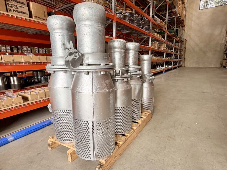
Fox Global has 8-inch and 6-inch flanged foot valves and Bauer fittings heading to a water treatment facility in the Northern Territory. This supply brings together components that perform different jobs within a pumping installation: foot valves support prime retention at the intake, while Bauer fittings provide practical connections between compatible sections of equipment, hose and pipework.
Getting the package right requires attention to how those components work together.
This guide follows the decisions from enquiry through delivery, installation and handover. It is written for project engineers, maintenance managers, procurement teams and operators who need equipment that arrives with its requirements understood.
The supply brief: what is known, and what needs a drawing
The confirmed project information establishes the product focus and destination.
| Confirmed detail | Project information |
|---|---|
| Valve sizes | 8-inch and 6-inch |
| Valve type | Flanged foot valves |
| Associated fittings | Bauer fittings |
| Destination | Northern Territory |
| Facility type | Water treatment |
In common nominal sizing, 6-inch equipment is generally associated with DN150 and 8-inch equipment with DN200. These descriptions do not establish exact internal diameters, flange dimensions or coupling profiles.
The project description also does not identify valve quantities, body materials, seal compounds, flange standards, working pressures or the particular water stream.
Those details belong in the approved specification. They should not be inferred from a photograph or from the fact that the equipment is going to a treatment facility.
A good supply brief therefore separates three things:
- What the site already knows.
- What the supplier needs to confirm.
- What the system designer or facility operator must approve.
That division helps avoid an assumption becoming an accidental design decision.
Treat each connection as an interface
For this type of package, the installation team may need to connect a foot valve to a flanged pipe, a flange adaptor to a Bauer connection, or a hose assembly to an existing coupling.
Each interface needs its own description.
A simple sketch showing connection type, nominal size, flow direction and equipment reference can be more useful than a lengthy list of loosely named fittings.
The purpose is not to complicate purchasing. It is to ensure that everyone is pricing and supplying the same arrangement.
Decision one: identify the water stream before selecting materials
“Water treatment” describes the facility, not necessarily the fluid passing through every component.
A treatment site may contain raw-water intake lines, process-water transfers, treated-water storage connections, recycled-water systems, backwash circuits and chemical-treatment equipment.
These duties are not automatically interchangeable.
Raw water can bring more than suspended dirt
An intake upstream of treatment may encounter changing solids levels, vegetation, mineral content or other source-water characteristics.
The specification should identify the water chemistry and the type of debris expected, together with seasonal or operational changes.
A visually clear source is not proof of chemical compatibility. Equally, cloudy water does not establish that a particular metal is unsuitable.
Use representative information from the actual service.
Treated water requires its own assessment
Treatment can change the water chemistry and introduce a residual disinfectant. Materials and seals need to suit the conditions where the component is installed.
If equipment is intended for contact with drinking water, ask for the applicable evidence of suitability and facility requirements. Do not treat the terms “water valve”, “stainless steel” or “galvanised” as evidence of drinking-water approval.
AS/NZS 4020 addresses products used in contact with drinking water. WaterMark certification is a separate product-certification consideration whose applicability depends on the product and installation. The project team should establish which evidence is required for the intended use.
Chemical-treatment lines are a separate duty
Water-treatment facilities may use concentrated chemicals that are substantially different from the treated water downstream.
A coupling suitable for a water-transfer line should not be reassigned to chemical dosing simply because its diameter matches.
Some published Bauer-style product guidance explicitly excludes chemical or hazardous-media duties. Approval must therefore come from the selected product’s technical information, rather than from a general description of the coupling system.
For the Northern Territory supply discussed here, the specific water stream has not been identified publicly. No drinking-water, wastewater or chemical-service approval is implied.
Have a water-treatment enquiry with several different services? Email the line descriptions and operating conditions to sales@foxglobal.com.au, or call Fox Global on 1300 852 795.
Decision two: define what the foot valve must achieve
A foot valve provides a non-return function at a pump suction intake.
During operation, it opens to allow water towards the pump. After shutdown, it closes against reverse flow and helps prevent the suction line draining back into the source.
This can support more reliable restarting where retaining a filled suction line is part of the pumping arrangement.
KSB describes foot valves as suction-line check valves, usually associated with strainers, and identifies their role in preventing the suction line running empty after the pump stops.
The valve does not perform every other function needed by the system.
Prime retention is different from initial priming
A conventional centrifugal pump installed above its source may still require filling and venting before startup.
The foot valve helps retain that liquid; it does not automatically make the pump self-priming.
The pump manufacturer’s instructions should define the filling, air-removal and restart procedure. KSB’s priming guidance distinguishes the submerged check function from the measures needed to fill a pump whose suction impeller is not flooded at standstill.
A foot valve is not an isolation plan
A non-return device should not be assumed to provide the positive isolation required for maintenance.
The site must establish how pressure, retained water and connected equipment will be controlled before opening a flange or coupling.
Likewise, a foot valve is not automatically a surge-control device or a substitute for a correctly selected discharge check valve.
Define its role clearly within the system rather than expecting it to solve every pressure or restart issue.
Ask how performance will be checked
Before ordering, decide what evidence the project needs.
That may include product data, a permitted installation orientation, pressure limitations, seat-leakage criteria or agreed test records.
A vague request for a “heavy-duty valve” does not tell the supplier how the component will be assessed or accepted.
Decision three: make the 6-inch and 8-inch duties explicit
A mixed-size package can be straightforward when each component has a clear equipment reference.
Problems arise when all items are described simply as “pump fittings” and their intended locations are left to interpretation.
The 6-inch and 8-inch foot valves should each be linked to the relevant intake or line duty. Associated Bauer fittings should be identified separately, including any size transitions.
Nominal diameter is not a flow rating
The size stamped on a component does not establish its permitted flow rate.
Hydraulic performance depends on the actual flow passage, valve opening, screen arrangement where fitted, operating conditions and the rest of the suction system.
The following calculation illustrates the difference between two assumed clear bores.
| Illustrative flow | Velocity through an assumed 150mm internal diameter | Velocity through an assumed 200mm internal diameter |
|---|---|---|
| 100m³/hr | 1.57m/s | 0.88m/s |
| 200m³/hr | 3.14m/s | 1.77m/s |
These are calculated average velocities using flow divided by circular area. They are not recommended duties or capacity ratings for the supplied valves.
Actual internal dimensions may differ from the nominal size, and local velocity through a valve or screen may be higher than the pipe-average value.
A larger valve is not automatically a complete solution
Increasing one component size may reduce its contribution to resistance, but an undersized adaptor, long suction hose or restrictive screen can remain.
Similarly, installing an 8-inch component on a 6-inch route introduces a transition that must be considered in the layout and hydraulic assessment.
Ask the supplier for performance data applicable to the selected valve. Compare the component at the required duty, rather than assuming that nominal diameter alone establishes suitability.
Record the operating range
Some installations run at one relatively steady duty. Others change with pump speed, source level or downstream demand.
Provide the normal flow, maximum intended flow and relevant operating range.
A valve should be assessed against the conditions it will actually encounter, including startup and shutdown where relevant.
Decision four: match the flange before the freight is booked
“Six-inch flanged” or “eight-inch flanged” is not a complete connection specification.
Flanges of the same nominal size can differ in drilling, pressure designation, dimensions and face arrangement.
A suitable valve body with the wrong connection still creates a site problem.
The minimum flange information
| Detail | What the supplier needs to establish |
|---|---|
| Nominal size | Intended pipe or equipment connection |
| Standard and designation | Specified flange system and rating |
| Bolt pattern | Hole count, hole diameter and pitch-circle diameter |
| Face arrangement | Compatible mating faces and gasket arrangement |
| Material | Suitability for the service and adjoining equipment |
| Fasteners | Required size, grade, length and corrosion considerations |
| Overall dimensions | Installation and maintenance clearance |
| Orientation | Access to bolts, coupling closures and serviceable parts |
Where identification is uncertain, provide photographs together with measured dimensions and any existing markings.
A photograph is a useful starting point. It is not a substitute for dimensional confirmation.
Resolve mismatches on paper
Do not plan to enlarge holes, force bolts or pull misaligned pipework into place during installation.
If an adaptor is needed, specify it before dispatch and check its impact on space, support and the flow path.
For flanged Bauer adaptors, both ends require identification. The flange description does not define the coupling profile, and the coupling size does not establish the flange drilling.
This is a particularly useful check when replacement equipment is being connected to an older installation.
Decision five: specify a complete Bauer connection
Bauer fittings are widely used where hose and pipe sections need practical connection and disconnection.
The coupling arrangement typically uses a male ball end, female socket, sealing ring and lever-operated closure. Exact components and terminology depend on the selected range.
BAUER’s original HK system is a proprietary product family. The market also includes Bauer-style alternatives. An enquiry should state whether genuine BAUER equipment or a particular approved alternative is required.
The term “Bauer” alone should not be used to assume manufacturer, compatibility or certification.
Check the complete set
A connection may require:
- The correct male component.
- The correct female component.
- A compatible closure or lever ring.
- The specified sealing ring.
- The appropriate hose tail, weld end, flange or other termination.
- Any locking provisions required by the product instructions.
Do not assume every component is included because the product name says “female fitting” or “coupling”.
For example, Dixon identifies some female Bauer-style spigots as supplied without the rubber sealing ring, which is sold separately. The quotation and packing list should make these inclusions clear.
Do not apply a range headline to every size
Product ranges may advertise a maximum working pressure that applies only to certain sizes or configurations.
Dixon’s Type B data, for example, publishes different pressure limits for smaller and larger size groups. That is a useful reminder to check the actual part, rather than relying on a general “up to” claim. It does not establish the rating of the fittings supplied for this Northern Territory project.
Pressure capability, vacuum suitability, temperature limits and permitted articulation should all be confirmed for the selected assembly.
Physical engagement is not proof of compatibility
A coupling that appears to close may still be an unsuitable combination.
Dixon’s quick-coupling guidance warns that some non-interchangeable components can connect physically and stresses matching the correct series.
Record the existing manufacturer, series and dimensions when replacing components. Avoid mixing unidentified parts from a stores bin simply because the closure can be engaged.
Decide where flanges and quick connections provide the most value
Flanges and Bauer connections solve different installation needs.
A flange can provide a defined bolted interface to fixed equipment. A suitable quick coupling can make planned removal or relocation more convenient.
Neither connection removes the need for support, correct assembly or isolation.
| Connection approach | Useful characteristics | Selection considerations |
|---|---|---|
| Bolted flange | Defined interface for fixed equipment and pipework | Standard, drilling, gasket, fasteners and assembly procedure |
| Bauer coupling | Practical connection and disconnection of compatible equipment | Matched components, seal, operating limits and closure access |
| Flanged Bauer adaptor | Transition between a flange and a coupling system | Both interfaces, adaptor dimensions and support |
| Purpose-built spool | Can resolve a specific layout or connection requirement | Approved drawing, materials, fabrication and inspection scope |
The best arrangement is often determined by how the equipment will be maintained.
If a foot valve needs periodic retrieval, identify the connection that will be opened and the equipment that will remain in place. Ensure the removal route works without dismantling unrelated pipework.
That conversation should occur before manufacture or mobilisation.
Decision six: account for the whole suction path
A foot valve and fittings form only part of the suction system.
Hose length, pipe diameter, bends, reducers, screens and source-water level all affect conditions at the pump inlet.
Every additional restriction must be included in the hydraulic assessment.
Available suction head is a system property
Net positive suction head available, or NPSHA, depends on the installation. It includes the effect of source pressure, liquid level, vapour pressure and suction losses.
The pump has its own NPSH requirement at the selected operating point.
The Hydraulic Institute includes losses through pipes, valves, fittings and entrances in the system assessment. It also explains why an appropriate margin above the pump’s published requirement is needed.
This means a valve cannot be assessed independently of the pump and suction layout.
Allow for changing conditions
A suction route that works with a high source level and clean intake may perform differently after the level falls or debris accumulates.
Provide the lowest intended operating water level and any credible changes in intake resistance.
The assessment should also consider the actual water temperature. For an open source, site elevation and atmospheric conditions can influence the available pressure head.
Do not use a generic maximum suction-lift figure as the sole basis for selecting the arrangement.
Positive-pressure sealing and vacuum duty are different checks
A suction connection can admit air without producing an obvious outward water leak.
For that reason, a visual inspection for dripping joints is not a complete suction-integrity assessment.
Confirm the permitted vacuum duty of the selected hose, fittings and seals, together with the appropriate test or commissioning method.
A pressure rating alone should not be treated as proof of suitability for every suction condition.
Decision seven: place the intake for the operating water level
The intake position needs to suit the lowest planned water level, not just the level observed during installation.
It also needs clearance from sediment and surrounding obstructions.
Submergence is more than keeping the opening wet
An intake can remain underwater and still draw air through a vortex.
The Hydraulic Institute’s intake guidance explains that minimum submergence depends on flow and intake geometry, with additional depth potentially needed to satisfy NPSH requirements.
There is no universal installation depth that can be assigned solely from the labels DN150 or DN200.
Review the approach flow, nearby walls, other intakes and the full operating level range.
Screening must suit the process
Where a strainer is included, establish what it is intended to exclude.
Coarse debris protection is different from fine filtration. A screen that protects an intake from larger objects may allow mineral fines or smaller particles to pass.
Check the pump’s solids capability and any downstream treatment requirements separately.
Also consider how the screen will be cleaned. Selecting smaller openings without allowing for obstruction and suction loss can exchange one problem for another.
The supplied valve’s actual strainer arrangement and opening size should come from its technical documentation.
Decision eight: plan for the Northern Territory location
The Northern Territory covers markedly different operating environments.
A coastal Top End site, an inland treatment installation and a remote community facility may have different exposure, access and maintenance conditions.
The project location should therefore be described more precisely than “NT” when finalising supply and freight.
Turn location into useful specifications
Relevant questions include:
- Will the equipment be continuously submerged or periodically drained?
- Is the installation exposed to salt-laden air or chemical splash?
- What ambient and water temperatures apply?
- Is equipment stored outdoors before installation?
- Are access routes or delivery arrangements seasonal?
- What lifting and unloading equipment is available?
- How quickly can replacement seals or fittings reach the site?
These are planning questions, not assumptions about the facility receiving this package.
Materials need the actual exposure conditions
Confirm the body, internal components, coatings, fasteners and seals separately.
If galvanised components are proposed, assess them against the actual water chemistry and exposure. Guidance from the Galvanizers Association of Australia identifies water composition, temperature and movement as factors affecting immersed coating performance.
If stainless steel is proposed, identify the grade and assess compatibility rather than relying on the word “stainless”.
A material suitable for one circuit may be unsuitable for another within the same facility.
Plan spares around consequence and access
The appropriate spare holding depends on what happens if a component becomes unavailable.
For some sites, approved spare sealing rings and closure components may be sufficient. For others, a complete replacement assembly may be justified.
Discuss the practical replacement time, storage requirements and correct part identification.
The objective is to make maintenance possible without encouraging unapproved substitutions.
The dispatch review: a small check with a large payoff
Before a package leaves the warehouse, reconcile the equipment against the agreed schedule.
Mixed 6-inch and 8-inch components should be identifiable without unpacking every item at the installation point.
| Dispatch check | What it prevents |
|---|---|
| Valve size and equipment reference | Sending the correct item to the wrong location |
| Flange details | Discovering a drilling mismatch at installation |
| Coupling components | Receiving incomplete connections |
| Seals and gaskets | Delays caused by small missing items |
| Identification and documents | Confusion over ratings or service assignment |
| Protective packaging | Damage to sealing faces and vulnerable parts |
| Package dimensions and mass | Problems with transport or unloading |
| Delivery contact and access details | Failed delivery or unsuitable handling arrangements |
Photographs can support the dispatch record, particularly for unusual adaptors or mixed packages.
They should complement the packing list and drawings, not replace them.
Protect cleanliness according to the service
The required cleanliness should be established before packing.
Protect open connections and sealing surfaces from transport contamination. Where drinking-water or other cleanliness-controlled duties apply, agree on the relevant preparation, packaging and handling requirements.
Do not assume that a component arriving visibly clean satisfies a defined cleanliness procedure.
Keep national freight expectations practical
Freight planning should account for the actual destination, carrier arrangements and site receiving capability.
Fox Global supports national supply, but delivery timing should be confirmed for the selected equipment and route rather than promised generically.
For a Northern Territory project, identifying the installation deadline early helps distinguish the required dispatch date from the required arrival date.
Commissioning should create a useful baseline
A successful first start is valuable, but it is not the whole handover.
The team needs to know what was installed, which limits apply and how normal operation looked at commissioning.
Record before starting
Check the identification, installation orientation, connection assembly, supports and intake position.
Confirm the filling and venting procedure, the required operating controls and the method for managing abnormal conditions.
Any pressure, leak or vacuum testing should follow an agreed procedure appropriate to the equipment and system.
Do not select a test pressure solely by applying a generic multiplier to a catalogue figure.
Observe during operation
Where instruments are available, record flow, suction pressure, discharge pressure, pump speed and source level.
Also note noise, vibration and visible evidence of air entry.
These observations provide a baseline for later troubleshooting. They are especially useful when the operating water level changes.
Check the planned shutdown behaviour
Where prime retention is required, verify that the system behaves as intended after a controlled shutdown and restart.
If the suction line loses its fill, investigate the entire route rather than assuming the new foot valve is the only possible cause.
Document any outstanding issues before the equipment is accepted as ready for routine service.
Handover belongs to the operators as well as the project team
A folder of documents is only useful if the people maintaining the system can find the relevant information.
A practical handover should identify:
- The location and service of each valve.
- The coupling manufacturer and series.
- Approved replacement seals and components.
- Applicable operating restrictions.
- The inspection and maintenance procedure.
- How to isolate, drain and retrieve equipment.
- Where drawings and test records are held.
- Who to contact for replacement supply.
Avoid recording every component under a vague name such as “Bauer fitting”.
Use enough detail that a stores or maintenance employee can identify the correct replacement without relying on the original installer.
Train around the actual connection
Operators should understand the approved method for closing, checking and disconnecting the selected coupling.
A difficult closure should prompt inspection for contamination, damage, wrong components or an unsuitable seal. It should not automatically prompt the use of more force.
Support the pipe or hose independently as required. Permitted coupling articulation is not permission to impose uncontrolled bending or unsupported loads.
When something changes: a focused troubleshooting table
Maintenance decisions improve when symptoms are linked to evidence.
| Symptom | Possible areas to investigate | Practical response |
|---|---|---|
| Pump loses prime after standing | Foot-valve leakage, air ingress or another drain path | Check the complete suction system |
| Bauer connection is difficult to close | Wrong seal, contamination, damage or mismatched components | Isolate and inspect before reassembly |
| Air appears during operation | Suction leaks, insufficient submergence or vortexing | Review connection integrity and intake conditions |
| Flow declines over time | Screen loading, lower water level or another restriction | Compare with commissioning readings |
| Flange leaks after installation | Gasket, alignment, fastener assembly or damaged faces | Inspect under controlled isolation |
| Coupling seal deteriorates repeatedly | Chemical exposure, temperature or incorrect installation | Reassess seal selection and operating conditions |
| Valve does not retain water | Debris, seat wear or closure damage | Inspect against the manufacturer’s criteria |
| Recurring vibration or noise | Air entry, suction conditions or pump-related causes | Obtain a system assessment |
The table provides investigation prompts, not a diagnosis.
A component may be affected by several conditions at once. For example, a loaded intake screen and falling water level can reduce suction performance together.
Keep photographs, readings and removed-part observations with the maintenance record.
For replacement valves, Bauer fittings or help clarifying an existing connection, contact Fox Global on 1300 852 795 or sales@foxglobal.com.au.
Australian project experience: useful lessons without copying the specification
Fox Global’s previous projects show how these product groups are used in practical fluid-transfer packages.
One documented South Coast quarry supply included 6-inch red layflat hose kits, rubber suction hose assemblies with Bauer fittings and galvanised Bauer strainers.
Another project involved 4-inch flanged tees with butterfly valves and Bauer fittings for a piling construction application.
These examples demonstrate the value of considering hoses, valves and fittings together.
They do not mean the same configuration is automatically suitable for a water-treatment facility. The new project still needs its own assessment of media, pressure, suction conditions, interfaces and documentation.
Avoid the “same as last time” shortcut
An existing part number is useful evidence, but it should not end the enquiry if the service has changed.
Ask whether the replacement serves the same water stream, operates at the same duty and connects to the same equipment.
Changes in pump speed, cleaning chemicals, intake location or operating levels may justify revisiting the specification.
Repeating a previous order is most effective when the conditions behind it are also understood.
Commercial clarity: what a complete quotation should show
A clear quotation makes both technical and purchasing decisions easier.
For 6-inch and 8-inch flanged foot valves and Bauer fittings, it should distinguish the valve scope from the connection accessories.
Confirm whether prices include strainers, gaskets, sealing rings, closure rings, fasteners, adaptors, documentation and freight.
Identify any proposed alternatives rather than treating them as invisible substitutions.
Compare equivalent packages
The lowest component price may not represent the lowest installed cost.
An alternative may omit accessories, require an adaptor or involve a different lead time. Another may offer a useful maintenance advantage that matters more than a small purchase-price difference.
Evaluate the package against the actual installation and service requirement.
Request current availability and realistic lead times. If the project needs special testing, coating, fabrication or identification, include it before the order is placed.
Working with Fox Global across Australia
Fox Global is proudly Australian-owned and family-operated, supporting customers with industrial hoses, valves, fittings and custom supply solutions.
Our approach combines fast response times, technical application support and straightforward communication. We help customers identify what is required, resolve missing details and coordinate supply around the project.
The Northern Territory package is one example of that practical approach: bringing together flanged foot valves and Bauer fittings with attention to how the equipment will connect and operate.
Fox Global supports customers across mining, civil construction, food and beverage, chemical processing, water treatment, manufacturing, agriculture, oil and gas, marine and waste management.
That broad experience reinforces the need to select equipment by service rather than by industry label alone.
National supply starts with clear information
From Sydney and regional NSW to Melbourne, Brisbane, Perth, Adelaide and the Northern Territory, the essentials remain the same: correct specifications, responsive service and delivery planning.
Send the equipment details, drawings, operating conditions and required arrival date.
Where information is incomplete, we can help identify the questions that need answering before supply is finalised.
Questions to resolve before issuing the order
Are 6-inch and DN150 always physically identical?
They are commonly corresponding nominal descriptions, but actual dimensions depend on the component and connection system. Confirm the drawing and mating equipment.
Does an 8-inch foot valve guarantee a particular flow?
No. Flow suitability depends on the valve geometry, losses, intake arrangement and pump duty. Use applicable performance data.
Are all Bauer fittings interchangeable?
Do not assume so. Confirm manufacturer, series, profile, size, seals and approved mating components.
Does a female Bauer fitting include its seal?
Not necessarily. Check the product description and quotation for the complete connection scope.
Can Bauer fittings be used on suction lines?
Appropriate products can be suitable, but confirm the vacuum capability of the selected fittings, seals, hose and attachment arrangement.
Are these products approved for drinking water?
No such approval is established by this project description. Confirm the intended water stream and obtain the evidence required for the specific products and installation.
Do foot valves remove the need to prime a pump?
No. They help retain water in an appropriate suction arrangement. Follow the pump manufacturer’s initial filling and venting requirements.
Can the same fittings carry treatment chemicals?
Only if expressly approved for the actual chemical duty. Water-service suitability does not establish compatibility with concentrated treatment chemicals.
Can Fox Global supply a complete connection package?
Fox Global can discuss the required valves, fittings, adaptors and associated hose or pipe connections, with scope and suitability confirmed against the application.
What should be included in an initial enquiry?
Provide sizes, quantities, water service, flow, pressure and vacuum conditions, temperatures, connection details, pump information, destination and deadline.
The final approval is about readiness to install
Before releasing a package, ask four practical questions.
Will it connect?
The flanges, coupling components and transitions are identified.
Will it suit the duty?
Materials, seals and operating limits have been reviewed against the actual service.
Can the site maintain it?
Access, retrieval, identification and spare-part requirements are understood.
Will it arrive ready for the team?
Packaging, documentation, freight and receiving arrangements are agreed.
That is the standard a useful supply package should meet.
For the 8-inch and 6-inch flanged foot valves and Bauer fittings heading to the Northern Territory, the wider lesson is simple: the component list is the beginning of the job. Clear interfaces and operating requirements turn it into an installation-ready supply.
Fox Global — Australian-owned, family-operated and ready to discuss your next water-treatment project.
Phone: 1300 852 795
Email: sales@foxglobal.com.au