The motor is running, the discharge line is waiting, and the operator expects water. Instead, the pump struggles to establish flow.
For a quarry maintenance team, this can trigger a familiar sequence: stop the equipment, check the water level, inspect the suction system and work out why a pump that operated yesterday will not restart normally today.
Sometimes the problem is a leaking connection. Sometimes it is an obstructed intake or a change in operating conditions. Sometimes the suction line has drained because the foot valve is no longer sealing.
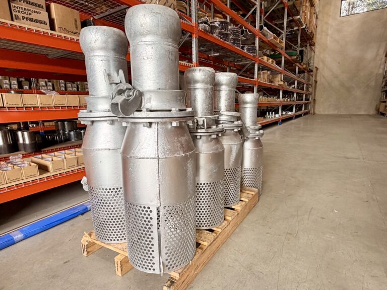
Fox Global has a 400mm galvanised foot valve heading to a quarry project in Central NSW. It is a substantial component, but its importance comes from its position in the pumping system rather than its physical size.
At the intake, a foot valve helps retain the water needed for reliable restarting. Its selection also influences suction losses, debris management and maintenance access.
The following guide examines those issues through the questions a quarry team would ask when diagnosing a troublesome pump. The project details are limited to the confirmed 400mm size, galvanised construction and Central NSW quarry destination; the operating scenarios and calculations are illustrative.
Start with the shutdown: where did the water go?
A conventional centrifugal pump operating above its water source generally needs the pump casing and suction line appropriately filled and vented before starting.
When the pump stops, the water in that suction line may try to drain back towards the source.
A foot valve provides a non-return function at the submerged intake. It opens to admit flow towards the pump and closes against reverse flow, helping retain the liquid column after shutdown. Foot valves are commonly used with suction strainers, although the exact arrangement depends on the selected product.
That retained water can reduce the need to refill a long suction line before each restart.
However, retaining prime depends on the complete installation. A foot valve cannot compensate for an air leak at another connection, an unsuitable priming arrangement or a damaged suction hose.
A foot valve supports priming; it does not create it
Installing a foot valve does not turn an ordinary centrifugal pump into a self-priming pump.
The initial filling and air-removal procedure still needs to follow the pump manufacturer’s instructions. KSB’s priming guidance distinguishes between retaining liquid with a submerged non-return valve and the filling or venting needed when the pump is above the source.
This distinction matters during commissioning.
If a new installation fails to establish flow on its first start, do not assume the foot valve is defective simply because it has not solved the priming problem. Confirm the pump arrangement and startup procedure first.
What reliable restarting means to a quarry
Quarry water systems can support pit dewatering, aggregate washing, dust-suppression supply and transfers between storage or settling areas.
An unreliable restart can interrupt the activity relying on that water, even if the pump itself remains mechanically serviceable.
For example, a transfer pump may stop overnight and restart before a wash plant begins operating. If the suction line has drained, the next shift must restore prime before the downstream process can proceed.
That is an illustrative quarry scenario, not a reported operating outcome from the Central NSW project. It shows why the intake valve belongs in a reliability discussion rather than being treated as an incidental pipe fitting.
Before blaming the valve, read the symptoms
Several suction-side problems can produce similar observations.
A pump that loses flow as the water level falls may have an intake-submergence problem. A pump that works well immediately after priming but struggles after standing may have a retention or air-ingress issue.
Neither observation provides a complete diagnosis on its own.
The first useful task is to establish when the problem occurs.
| Observation | Questions worth asking |
|---|---|
| Pump struggles only after standing | Has the suction line drained? Can air enter through joints or seals? |
| Flow deteriorates as the source empties | Has suction lift increased? Is the intake approaching its minimum submergence? |
| Performance changes after rain | Has debris accumulated? Has the solids load or intake position changed? |
| Pump becomes noisy at higher flow | Are suction losses, air entry or cavitation contributing? |
| Cleaning the intake temporarily restores performance | Is screen loading recurring? Is the intake too close to sediment? |
| The same replacement valve fails repeatedly | Is the surrounding system causing the damage or preventing closure? |
Take observations before changing several components at once.
Record the source level, operating speed, flow if measured, suction and discharge readings, and the time since the previous shutdown. Also note recent maintenance and changes to the pipe route.
A short operating history often gives a supplier more useful information than “the pump is not drawing properly”.
For help identifying the information needed for a replacement enquiry, contact Fox Global on 1300 852 795 or email sales@foxglobal.com.au.
Why 400mm is a connection size, not a guaranteed capacity
A 400mm foot valve is a large-bore component, commonly discussed as DN400 nominal size. That does not mean every internal passage measures exactly 400mm or that every valve of that nominal size has the same hydraulic performance.
The body shape, closure mechanism, available opening and any strainer all influence the flow path.
A supplier therefore needs more than the existing pipe diameter to assess suitability.
The required flow, pump characteristics, suction arrangement and acceptable head loss belong in the selection process.
A simple calculation puts diameter into perspective
For a circular passage, average velocity is calculated from flow divided by cross-sectional area.
Using an assumed actual internal diameter of 400mm, the area is approximately 0.1257m².
| Illustrative flow | Flow in litres per second | Average velocity in the assumed 400mm passage |
|---|---|---|
| 500m³/hr | 138.9L/s | 1.11m/s |
| 750m³/hr | 208.3L/s | 1.66m/s |
| 1,000m³/hr | 277.8L/s | 2.21m/s |
These figures are mathematical examples. They are not capacity ratings, recommended duties or confirmed performance figures for the supplied valve.
They also describe average velocity in the assumed circular passage, not the local velocity through a valve opening or strainer.
A manufacturer’s pressure-loss curve, flow coefficient or other suitable performance data is needed to assess the actual component.
Why a larger connection can still contain a restriction
Two valves with the same flange size may have different internal geometries.
One may provide a relatively open flow path, while another has a more restrictive closure arrangement or less effective strainer area. The effect becomes more important as the required flow increases.
For procurement, the useful comparison is therefore not simply “400mm versus 400mm”.
It is the specified valve’s performance at the required duty, together with its materials, sealing arrangement and installation requirements.
The hidden cost sits on the suction side
A foot valve introduces resistance to flow. So do suction pipes, bends, reducers, strainers and other fittings.
Those losses matter because they reduce the pressure available at the pump inlet.
In pump terminology, net positive suction head available, or NPSHA, describes the inlet conditions available from the system above the liquid’s vapour-pressure head. The pump has its own NPSH requirement at the selected operating point.
The installation needs an appropriate margin, established with the pump supplier or responsible engineer. Matching NPSHA to a published NPSH3 value is not a guarantee of cavitation-free operation; NPSH3 relates to a defined performance reduction during testing.
Think in terms of a suction-head allowance
For an open water source, a simplified assessment considers:
- Atmospheric pressure at the site.
- Water level relative to the pump.
- Water temperature and corresponding vapour pressure.
- Friction and entrance losses throughout the suction system.
- The pump’s requirements at the intended flow and speed.
The foot valve is one part of that calculation.
A remote intake, long hose run and several fittings can collectively consume more of the available suction-head allowance than expected. The Hydraulic Institute specifically includes pipe, valve, fitting and entrance losses in suction-side assessments.
Compare the new system with the dirty system
A clean strainer is only the starting condition.
If debris gradually obstructs the intake, suction losses can increase during operation. A system that works comfortably immediately after cleaning may become unreliable before the next scheduled inspection.
An illustrative comparison makes the issue clear:
| Hypothetical condition | NPSHA | Assumed pump NPSH3 | Difference |
|---|---|---|---|
| Clean intake | 6.0m | 3.5m | 2.5m |
| Partially obstructed intake | 4.2m | 3.5m | 0.7m |
These invented figures demonstrate how changing intake resistance can reduce the difference between available and required suction head. They do not establish an acceptable margin for a real pump.
The required margin depends on the pump and application. Manufacturer guidance is essential, particularly where the operating point moves across a wide flow range.
The practical lesson is to include deteriorating intake conditions in the design discussion, rather than assessing only a newly installed valve in clean water.
Follow the water level, not just the original drawing
Quarry sumps and storage areas do not necessarily remain at one level.
Rainfall, pumping, process demand and changes in site drainage can alter the depth above an intake. Sediment accumulation can also change the relationship between the intake and the bottom.
The valve needs a position that remains suitable across the intended operating range.
Submerged does not always mean sufficiently submerged
An intake can remain visibly underwater while still drawing air through a surface vortex.
The Hydraulic Institute identifies minimum submergence as a consideration for preventing strong air-core vortices entering pump intakes or suction piping. The requirement depends partly on flow and intake geometry, and may need to increase to satisfy NPSH requirements.
There is no defensible universal immersion depth for every 400mm foot valve.
A shallow, wide pond with uneven approach flow is different from a purpose-designed sump. Nearby walls, other intakes and incoming streams can also affect conditions.
Xylem’s engineering guidance similarly distinguishes vortex suppression from satisfying NPSH and notes that less-than-ideal inlet conditions may require additional submergence.
Keep the intake clear of the bottom
Placing an intake directly on settled fines can increase the solids entering the system and make obstruction more likely.
At the other extreme, positioning it too close to the surface may create air-entry problems as the level falls.
The installation must balance minimum submergence, bottom clearance and access. KSB’s foot-valve guidance specifically calls for suitable distance from both the sump floor and the lowest suction-side water level.
For an evolving quarry sump, reassess those clearances after desilting, relocation or significant changes in water level.
The original installation measurement should not become a permanent assumption.
Separate debris exclusion from water treatment
A strainer associated with a foot valve can prevent certain larger objects entering the suction system. It does not make dirty water clean.
Sand, fine silt and particles smaller than the openings may still pass through.
This distinction affects both pump selection and downstream equipment. A valve that excludes stones or larger debris may provide little protection against abrasive fines or particles capable of blocking small spray nozzles.
Ask what the screen is intended to stop
Specify the debris of concern rather than requesting “a fine strainer”.
The useful questions include:
- What is the largest particle the pump can accept?
- Are leaves, vegetation or fibrous materials present?
- How much suspended mineral material is expected?
- Is downstream filtration required?
- How often can the intake realistically be retrieved and cleaned?
- What happens if the screen becomes partially obstructed?
Opening size and effective open area are separate considerations.
A screen with many small openings may exclude more debris but require more cleaning. A coarser arrangement may create less restriction while allowing more solids through.
The correct balance depends on the whole system.
Avoid improvised screen modifications
Wrapping fine mesh around an existing intake can appear to solve a debris problem quickly.
It also changes the hydraulic conditions. The additional material may block rapidly or create more suction loss than the original arrangement allowed.
Similarly, enlarging screen openings without reviewing the pump’s solids capability can expose downstream equipment to material it was not selected to handle.
Treat screen modifications as changes to the intake design, not routine workshop adjustments.
Galvanised construction: useful protection with environmental limits
Galvanising provides a zinc coating that protects the underlying steel. For suitable applications, this can offer a practical combination of corrosion protection, structural capability and cost.
However, “galvanised” is not a guarantee of unlimited immersed life.
The confirmed project description is a galvanised foot valve. The exact coating process, coating thickness and applicable certification should be established from the product documentation.
Where hot-dip galvanising is specified, its performance must still be assessed against the water and service conditions.
Water chemistry changes the answer
The Galvanizers Association of Australia identifies pH, temperature, exposure and water movement as factors affecting zinc corrosion under immersion. Water composition also affects whether protective deposits form.
For a quarry intake, useful information may include pH, conductivity, salinity, chlorides, temperature and relevant process contaminants.
Do not assume that water is chemically mild because it looks clear. Conversely, cloudy water does not by itself establish that galvanised construction is unsuitable.
Obtain representative information from the actual source.
If different sources are combined, assess the resulting water rather than relying on a report for one incoming stream.
Abrasion is a different mechanism from corrosion
Galvanising provides corrosion protection, but abrasive particles can still contribute to wear.
The American Galvanizers Association notes that flow conditions and abrasion influence performance in water environments. A highly abrasive duty requires its own assessment rather than relying on general corrosion-resistance claims.
This is particularly important when water carries persistent mineral fines or the intake is repeatedly dragged across a gritty surface.
Avoid quoting a service life without the necessary environmental and operating evidence.
The seal needs attention too
The coating on the body does not determine the suitability of the valve seat or other internal components.
Confirm the materials used in the closure and sealing arrangement. Consider water chemistry, temperature, debris and any cleaning products.
A mechanically sound body with a worn or obstructed seat may still fail to retain prime.
Three water duties that should not share one assumption
A Central NSW quarry may have several water circuits with different conditions. The examples below illustrate common selection distinctions; they are not additional claims about this project.
| Illustrative duty | Main issue to examine | Foot-valve selection implication |
|---|---|---|
| Rainwater collected in an excavation sump | Changing levels and debris after runoff | Review intake position, screening and inspection access |
| Recovered water transferred from a settling area | Fine solids and variable sediment conditions | Assess abrasion, obstruction and pump compatibility |
| Stored water feeding a dust-suppression system | Reliable restart and downstream nozzle requirements | Separate prime retention from the filtration needed downstream |
A valve selected for one circuit should not be moved into another solely because the flange fits.
Record the assigned service and reassess material and hydraulic suitability before reassignment.
The same principle applies when a temporary dewatering installation becomes a long-term process-water supply. A longer operating period may change maintenance expectations and justify a more permanent intake arrangement.
What to confirm before a DN400 valve reaches site
At this size, a connection mismatch can create substantial delays.
The nominal bore does not establish the flange drilling, pressure class, outside dimensions or valve envelope.
For the current Central NSW project, the flange details and internal mechanism have not been specified here. They must be confirmed through the actual supply documentation.
Use a dimensional check, not visual recognition
Where the valve is flanged, request a drawing showing the connection details and overall dimensions.
| Item to confirm | Reason it matters |
|---|---|
| Nominal connection size | Establishes the intended pipe interface |
| Flange standard and drilling | Prevents incompatible bolt patterns |
| Pressure class and applicable limits | Confirms the required operating envelope |
| Face arrangement and gasket | Supports a suitable sealed joint |
| Overall height and width | Checks installation and retrieval clearance |
| Mass and centre of gravity where relevant | Supports handling planning |
| Permitted orientation | Ensures the closure works as intended |
| Strainer arrangement, if fitted | Establishes debris-exclusion and access requirements |
| Closure and seat materials | Supports compatibility and maintenance planning |
| Head-loss data | Allows the component to be included in hydraulic assessment |
Do not use bolts to pull substantially misaligned pipework into place.
The pipe supports and valve installation should suit the assembled geometry without relying on the flange joint to correct an unsuitable arrangement.
Pressure duty includes more than running suction
The valve may experience different conditions when operating, stopped, filled, tested or exposed to a transient event.
Confirm the applicable forward-flow, reverse-head and pressure limitations. Do not assume a suction-side location makes pressure rating irrelevant.
For long lines or unusual shutdown behaviour, ask whether transient analysis is needed. A foot valve is not automatically a surge-control device.
Send drawings, operating details and the required delivery date to sales@foxglobal.com.au. Fox Global can help clarify the valve and connection requirements before the order is finalised.
Choose the arrangement before choosing the replacement
Replacing like for like is convenient when the existing selection remains suitable.
It is less useful when the same arrangement repeatedly loses prime, blocks or requires difficult retrieval.
| Arrangement | Potential advantage | Main consideration |
|---|---|---|
| Submerged foot valve with suitable screening | Can retain the suction-line water column | Adds suction loss and requires access for servicing |
| Open screened intake with compatible priming equipment | Removes the submerged check function from the intake | Requires a suitable priming system and operating method |
| Flooded-suction installation | Can simplify inlet and priming conditions | Requires suitable pump location, layout and protection |
| Submersible pump arrangement | Changes the need for an above-water suction line | Requires a different pump, electrical and maintenance assessment |
These are system options, not interchangeable fittings.
A self-priming pump may still have manufacturer-specific requirements concerning retained liquid and intake arrangements. Likewise, a discharge check valve does not automatically perform the same role as an intake foot valve.
Discuss alternatives with the pump supplier and responsible designer before changing the system.
For a quarry with an established, serviceable suction arrangement, a properly selected replacement foot valve may remain the most practical solution.
Installation day should include the retrieval plan
A large foot valve must be installed in a way that also allows it to be serviced.
The time to work out how to retrieve it is before it is submerged beneath an operating intake.
Obtain the actual mass, approved lifting information and installation instructions. Consider the assembled pipework and any retained water, rather than planning around the dry valve alone.
Do not assume the strainer basket or another convenient feature is a lifting point.
A practical sequence for the project team
Before delivery: confirm drawings, handling access, connection details and the receiving arrangements.
At receipt: check identification, visible condition and the supplied components against the order. Resolve discrepancies before mobilisation.
Before lowering: confirm orientation, supports, intake clearances and the intended low-water operating limit.
Before starting: complete the pump manufacturer’s filling, venting and commissioning procedure.
During initial operation: establish baseline readings and observe flow stability, water level and any abnormal behaviour.
After a controlled shutdown: verify that the system behaves as intended and assess retained-prime performance using the agreed procedure.
These steps should be adapted to the site’s equipment and work controls.
Make maintenance access visible on the drawing
Show the retrieval route, lifting access and space required for opening or removing serviceable parts.
Also consider where the valve will be inspected and cleaned after removal. A maintenance area that can contain drained water and debris is preferable to improvising beside a sump.
The ability to service a component can strongly influence its practical operating cost.
Fault-finding without replacing parts blindly
When performance changes, compare the symptoms with the commissioning baseline.
| Symptom | Possible causes | Useful investigation |
|---|---|---|
| Loss of prime after shutdown | Valve leakage, trapped debris, suction air leak or another drain path | Check retention and inspect the complete suction system |
| Difficult first startup | Incomplete filling, trapped air or unsuitable priming arrangement | Follow the pump’s commissioning procedure |
| Falling flow during operation | Screen loading, lower source level, restriction or changed pump conditions | Compare level, flow and pressure readings |
| Intermittent air in the system | Vortexing, insufficient submergence or air leakage | Review intake conditions and suction integrity |
| Persistent valve-seat leakage | Wear, damage or material trapped at the closure | Retrieve and assess against service criteria |
| Noise or vibration | Air entry, cavitation, pulsation or mechanical problems | Obtain a system assessment rather than assuming one cause |
| Rapid external deterioration | Unsuitable water chemistry, coating damage or abrasive handling | Review materials, exposure and maintenance history |
| Repeated debris obstruction | Intake location or screen arrangement unsuitable for the source | Reassess screening and cleaning access |
A symptom may have more than one cause.
For example, a partially obstructed strainer and a falling water level can occur together. Replacing only the valve may leave the underlying problem unresolved.
Record what was found during removal, including photographs and the location of wear or debris. This makes the next maintenance decision more informed.
Maintenance should respond to conditions
A fixed inspection interval is useful only if it suits the actual duty.
An intake exposed to changing sediment or runoff may need different attention from one operating in a relatively controlled storage tank.
Use operating experience, manufacturer instructions and the consequences of failure to set the programme.
Build checks around meaningful events
In addition to scheduled inspections, consider checks after:
- Significant changes in source-water conditions.
- Relocation of the intake or pump.
- Unexpected loss of prime.
- Abnormal noise, vibration or flow.
- A known impact or handling incident.
- Extended shutdowns.
- Changes to the screen or suction pipework.
Keep records of cleaning, replaced parts and observed deterioration. If the time between blockages is shortening, investigate the source conditions instead of simply cleaning more often.
Protect the galvanised surface during cleaning
Select cleaning methods appropriate to the coating and contamination.
The Galvanizers Association of Australia recommends suitable gentle cleaning practices and identifies hard plastic bristles where mechanical scrubbing is needed. Aggressive cleaning should not be assumed harmless to the protective surface.
Any coating repairs should follow the applicable product and coating requirements.
Do not treat cosmetic appearance alone as an acceptance criterion. Inspect functional surfaces and serviceable parts against the manufacturer’s guidance.
Keep the right spare information
A spare seat or seal is only useful if the team can identify it correctly.
Maintain the valve model, drawing reference, parts list and supplier details with the asset record. For critical service, discuss suitable spares and replacement lead times before a failure occurs.
An accurately documented valve can be reordered more efficiently than an unidentified component retrieved from a sump.
Compare the quotation with the cost of using it
The purchase price is one part of the decision.
A quotation should make clear what is included: valve, strainer if applicable, mating components, gasket, fasteners, documentation, packaging and freight.
Also compare access to spare parts and the time required to remove, inspect and reinstall the unit.
Hydraulic performance belongs in the commercial discussion because avoidable restriction can affect the system duty and operating efficiency.
Documentation should answer specific questions
Ask for the evidence the project requires, rather than requesting a generic “certificate”.
Possible requirements include dimensional drawings, material information, coating documentation, pressure or seat-test records, and operating instructions.
Where hot-dip galvanising to AS/NZS 4680 is specified, agree on the documentation required before supply. GAA guidance distinguishes coating conformance information from additional coating-thickness test documentation requested and agreed beforehand.
A coating certificate does not establish valve flow capacity, sealing performance or complete-system compliance.
Each document should have a clear purpose in the acceptance process.
Fox Global: regional project support with national reach
Fox Global is a proudly Australian-owned and family-operated business supporting industrial hose, valve and fitting requirements.
For a project such as this 400mm galvanised foot valve heading to Central NSW, our role includes helping customers clarify the specification, checking supply requirements and communicating around the required timeframe.
Fast responses matter, particularly when a maintenance team is trying to distinguish an urgent replacement from a wider installation problem.
Technical expertise and customer service are most useful when they turn incomplete information into a clear enquiry: what is required, where it will operate and what must be confirmed before dispatch.
Experience across different operating environments
Fox Global supports customers across mining, civil construction, food and beverage, chemical processing, water treatment, manufacturing, agriculture, oil and gas, marine and waste management.
That range reinforces the importance of application-specific selection.
A quarry intake, an agricultural transfer line and a chemical-process connection may share a nominal diameter while requiring different materials, connections and documentation.
Our custom solutions approach focuses on the actual requirement rather than assuming one product configuration suits every industry.
Sydney, Central NSW and Australia-wide supply
From our Western Sydney base, Fox Global supports customers seeking industrial valves in Sydney and regional NSW, as well as Melbourne, Brisbane, Perth, Adelaide and other Australian locations.
National supply requires practical planning: clear dimensions, suitable packaging, receiving equipment and realistic freight allowances.
Availability and lead time depend on the selected valve and project scope. Provide the site location and required delivery date early so these can be considered alongside the technical requirements.
For enquiries, call 1300 852 795 or email sales@foxglobal.com.au.
The questions that tend to arrive after the quotation
Does a foot valve stop a pump losing prime?
It helps retain the suction-line water column, provided it seals correctly. The rest of the suction system must also be suitable and free from air leaks or unintended drain paths.
Is a 400mm foot valve suitable for every 400mm suction line?
No. Confirm actual flow requirements, connection details, pressure limitations, installation orientation, materials and head loss.
Can a galvanised foot valve handle quarry water?
Potentially, but “quarry water” is not a complete fluid specification. Water chemistry, solids, temperature and abrasion need assessment for the selected product.
Is a foot-valve strainer a filter?
It is generally intended to exclude specified larger debris. It does not provide fine filtration unless expressly designed and rated for that purpose.
How far below the surface should the valve sit?
There is no universal depth. Minimum submergence depends on intake geometry, flow and operating conditions, and must also be consistent with pump suction requirements.
Should the valve sit on the sump floor?
The intake requires appropriate bottom clearance. Sitting in accumulated sediment can increase obstruction and solids intake.
Can a larger pump overcome a restrictive intake?
It should not be assumed to solve the problem. Changing the pump can change flow, suction losses and NPSH requirements. Assess the complete system first.
What is the expected service life?
It depends on construction, water conditions, wear, operating duty and maintenance. A general lifespan cannot be assigned from nominal size and galvanised finish alone.
What information does Fox Global need to quote?
Start with quantity, required flow, pump details, suction layout, water conditions, connection drawing, delivery location and deadline. Identify any required testing or documentation.
Leave the next shift a system they can understand
A well-selected foot valve should be part of a clear operating arrangement: the intake position is known, the low-water limit is understood, the suction system is documented and the valve can be retrieved for maintenance.
That is what makes a large component useful over time.
The 400mm galvanised foot valve heading to this Central NSW quarry project highlights a straightforward procurement lesson: start with the water source and pumping duty, then confirm the component.
When the next shift starts the pump, reliable flow should follow from a suitable, maintained system—not another round of guesswork.
Discuss your quarry valve requirements with Fox Global.
1300 852 795
sales@foxglobal.com.au